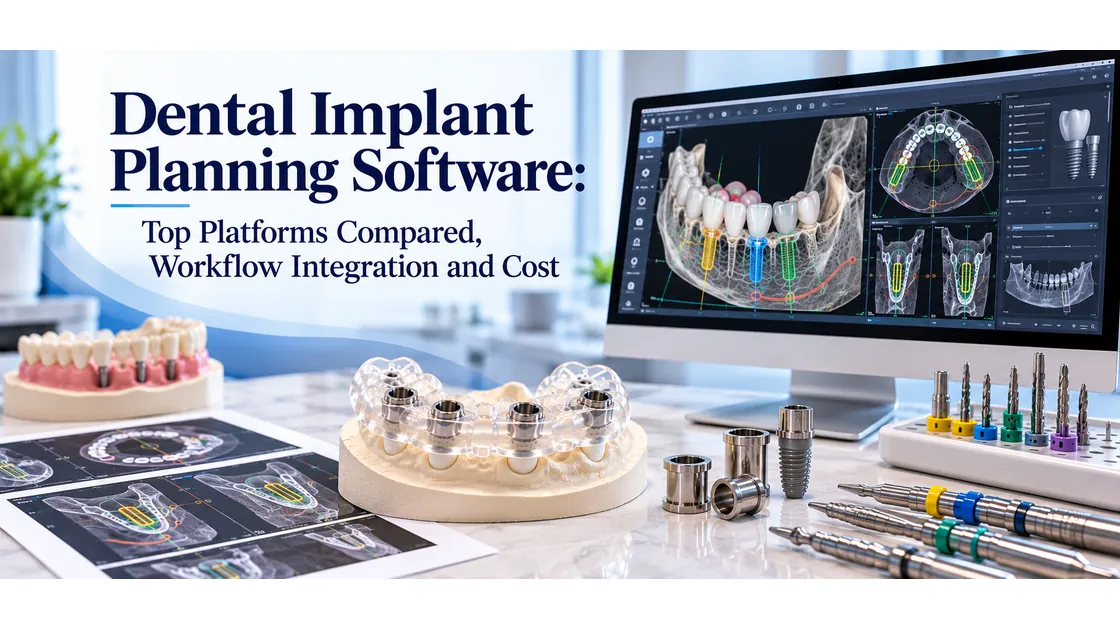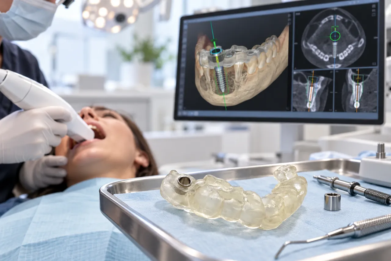
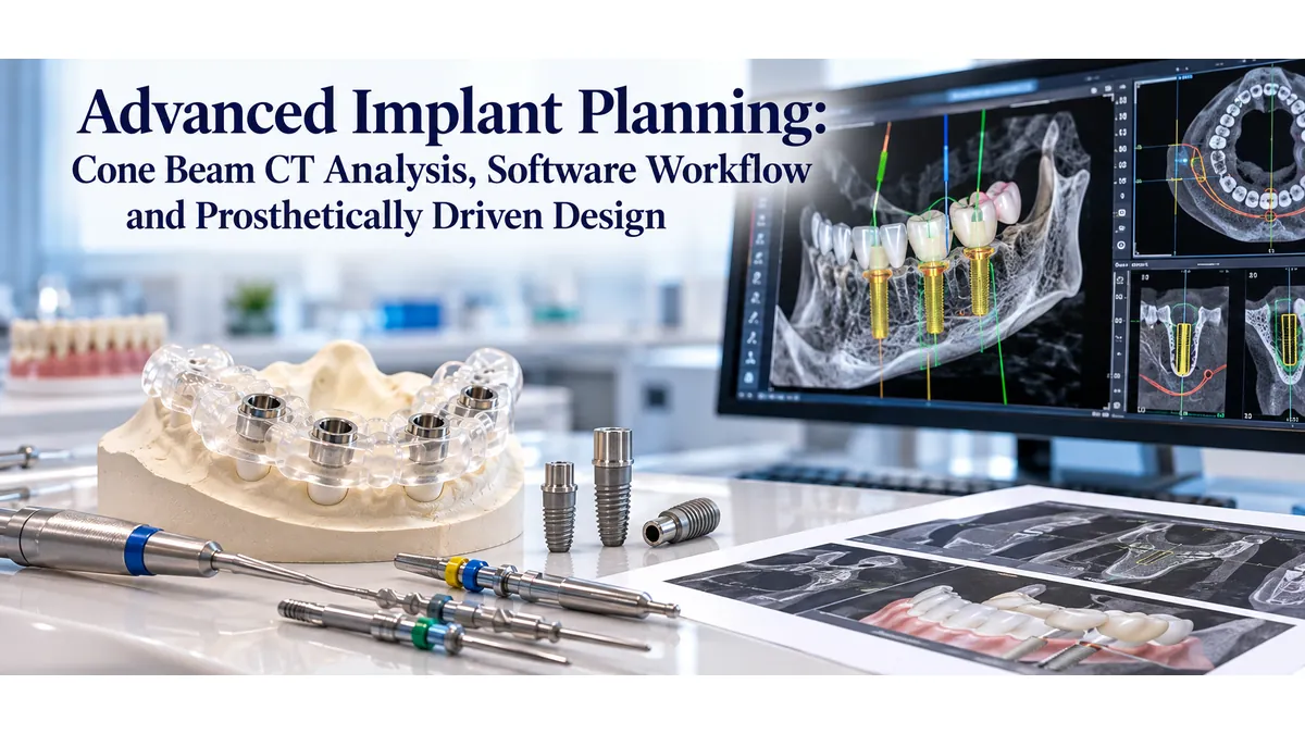
Planning an implant case used to begin with the bone. Clinicians assessed the available ridge, identified where bone existed, and placed implants where anatomy permitted. That approach sometimes worked, but it often produced restorations that compensated for poor positioning rather than emerging from ideal design. Today, the most predictable implant outcomes begin with the final restoration and work backward, using custom surgical guides for dental implants to transfer that digital plan precisely into the surgical field.
This guide explains the full advanced implant planning workflow: from cone beam computed tomography analysis to software-based virtual placement, scan merging, and the prosthetically driven design philosophy that makes every step meaningful. Whether you are refining your workflow or evaluating a new digital system, understanding how planning decisions shape surgical and prosthetic outcomes will help you get more from every guided case.
What Prosthetically Driven Implant Planning Means
Starting With the Restoration, Not the Bone
Prosthetically driven planning means the position of the implant is chosen first by the required position of the final crown, not by where bone happens to be. The restorative team defines the tooth position based on occlusion, aesthetics, emergence profile, and adjacent tooth relationships. That position then becomes the target for the implant platform.
This approach requires knowing the prosthetic outcome before opening the surgical planning software. A diagnostic wax-up or digital smile design, converted into a radiographic guide or a digital tooth library position, gives the planning software a fixed target. The implant is then placed to support that prosthetic goal, with bone assessment informing how close the team can get rather than dictating the starting point.
Why Implant Position Matters More Than Bone Availability
An implant placed where bone is abundant but prosthetically compromised creates long-term problems: off-axis loading, difficult hygiene access, poor emergence profile, and restoration instability. These complications rarely show up on the day of delivery. They surface months or years later, often requiring corrective treatment that could have been avoided with better upfront planning.
Prosthetically driven placement distributes load along the long axis of the implant, creates space for natural-looking contours, and simplifies the restorative phase. When the implant is where the restoration needs it to be, the laboratory work becomes more straightforward and the final result more durable.
Cone Beam Computed Tomography Analysis: Reading the 3D Data
Bone Volume and Density Assessment
A cone beam computed tomography scan provides three-dimensional data that a two-dimensional periapical or panoramic image cannot match. For implant planning, the critical measurements are bone height (the distance from the crest to an anatomical boundary such as the inferior alveolar canal or sinus floor), bone width at the crest and at various depths, and bone density.
Bone density in a cone beam computed tomography scan is assessed by comparing the relative grayscale values of trabecular and cortical bone patterns. Dense, compact cortical bone appears bright and provides stable initial fixation. Trabecular bone quality ranges from dense (type 2) to very porous (type 4), which influences healing time, implant diameter selection, and loading protocols. Identifying low-density sites preoperatively allows the surgeon to adjust the plan rather than discover the issue intraoperatively.
Identifying Anatomical Boundaries
Every implant site has boundaries that limit safe placement: the inferior alveolar nerve and mental foramen in the mandible, the maxillary sinus and nasal floor in the maxilla, the lingual plate in posterior mandibular sites, and the buccal plate in anterior esthetic zones. Cone beam computed tomography scanning allows the clinician to measure safety margins to each of these structures in all three planes simultaneously.
Cross-sectional views at 1-millimeter intervals are standard. The software marks a buffer zone around critical anatomy, typically 2 millimeters from the inferior alveolar canal, and the virtual implant must stay within that boundary. Reviewing these cross-sections before the design consultation with your surgical guide design services provider ensures the plan accounts for all anatomical constraints.
What to Flag Before Moving Forward
Not every cone beam computed tomography scan produces a straightforward planning case. Sites to flag before beginning software-based design include significant bone defects that may require grafting, proximity of the inferior alveolar nerve that falls within the safety buffer, sinus floor irregularities that could complicate a sinus augmentation decision, and pathology (cysts, retained root tips, periapical lesions) that requires treatment before implant placement.
Flagging these conditions at the analysis stage, rather than during guide design, prevents wasted effort and additional revisions.
The Radiographic Guide and Scan Merge Process
Designing and Using a Radiographic Guide
A radiographic guide is a duplicate of the existing prosthetic tooth position, fabricated from clear acrylic and loaded with radiopaque markers such as barium sulfate or gutta-percha spheres. When the patient wears the guide during the cone beam computed tomography scan, the desired tooth positions appear in the three-dimensional data alongside the bone anatomy.
This direct overlay method eliminates the guesswork of estimating prosthetic position from bone anatomy alone. The radiopaque markers in the guide become reference points that the planning software can recognize. The result is a scan that shows both the available bone and exactly where the restoration needs to sit, making prosthetically driven virtual implant positioning significantly more accurate.
Merging the Cone Beam Computed Tomography and Intraoral Scan
Modern planning platforms support the merging of cone beam computed tomography data (exported in DICOM format) with intraoral scans or desktop scans of the patient's dentition (exported in STL format). The merge aligns these two datasets at common reference points, typically existing tooth surfaces visible in both files.
The merged dataset gives the planning software a complete picture: the three-dimensional bone anatomy from the cone beam computed tomography, the exact surface geometry of the patient's teeth from the intraoral scan, and the prosthetic target from the radiographic guide or a digitally positioned tooth library file. Many implant surgical guide lab workflows begin at this point, receiving the merged file from the clinician and proceeding with virtual design.
Software Workflow Step by Step
Importing and Orienting Data
Planning software options used in implant dentistry include Implant Studio, coDiagnostiX, Simplant, and Blue Sky Plan. All follow a similar import and alignment workflow. The cone beam computed tomography DICOM file is imported first, and the software generates a three-dimensional model of the bone segmented from the scan. The intraoral scan STL is then imported and aligned to the bone model.
Orientation is critical at this stage. The bone model must be oriented to reflect the patient's natural occlusal plane and midline. Misalignment here cascades into every downstream step, including virtual implant placement and guide design. Most software includes tools to set orientation landmarks before proceeding.
Virtual Implant Placement
With the merged dataset properly oriented, the clinician places a virtual implant replica from the manufacturer's library. The replica matches the exact dimensions and thread geometry of the physical implant that will be used in surgery. The software calculates angulation, depth, and proximity to adjacent teeth and critical anatomy in real time.
The goal at this stage is to achieve the position that supports the prosthetic target while respecting bone boundaries. The software flags any collisions with anatomical structures or adjacent implants. Once the position is confirmed, the planning software calculates the precise drill path that the surgical guide must transfer. This drill path becomes the specification for dental implant guide fabrication at the lab.
Generating the Surgical Guide Design
When virtual implant positions are finalized, the planning software generates a surgical guide design around them. The guide is designed to seat on the patient's teeth, mucosa, or bone, depending on the support type selected. Sleeve positions are placed at the virtual implant locations, with internal diameters matched to the drill system being used.
The guide design file (typically in STL format) is then exported and sent to the fabrication lab. Submitting through a clear surgical guide submission process that includes the guide design file, the merged scan file, and the implant manufacturer's drill protocol allows the lab to verify the design and begin fabrication without back-and-forth delays.
Common Planning Errors and How to Avoid Them
Misaligned Scan Data
The most common planning error is a poorly aligned merge between the cone beam computed tomography data and the intraoral scan. When the two datasets do not align accurately, the virtual implant position is based on incorrect anatomy. The surgical guide then places the implant in the wrong location relative to both the bone and the prosthetic target.
Alignment accuracy depends on having sufficient common reference points (typically at least three teeth visible in both datasets), high-quality scan data with minimal artifact, and verification of the alignment at multiple cross-sectional views before proceeding. If the merge looks off at even one viewing angle, it should be redone.
Ignoring Prosthetic Space
A virtual implant placed in ideal bone position but without checking prosthetic space requirements will create a restorative problem. The implant platform must have enough vertical clearance for the abutment and the crown material. Tissue-level implants have different emergence profiles than bone-level implants with angled abutments. Reviewing the prosthetic space in the planning software before finalizing the design prevents mismatched component orders and restorative compromises.
Failing to Account for Adjacent Anatomy
Adjacent tooth roots, furcations in multirooted teeth, and implant platforms from previously placed implants all define limits on the available space. Planning software calculates minimum spacing requirements from each of these structures (typically 1.5 millimeters from an adjacent root and 3 millimeters between two implant platforms). Working within these parameters at the planning stage prevents dehiscence, fenestration, and prosthetic crowding. Understanding the surgical guide fabrication workflow helps clinicians know which parameters the lab will verify on their end.
What Happens After You Submit Your Plan
Lab Review and Quality Checks
When a completed planning file arrives at the lab, the first step is a technical review of the design. The review checks that all sleeves are placed correctly relative to the intended implants, that sleeve inner diameters match the drill system protocol, that the guide support surface fits the anatomy in the merged scan, and that wall thickness is sufficient for structural integrity during drilling. This review step, provided by implant surgical guide specialists, prevents guides from being fabricated with design errors that would only be discovered chairside.
If the lab identifies a concern, such as a sleeve positioned too close to an adjacent tooth or a support surface that does not match the intraoral scan geometry, they contact the clinician before fabricating. This communication step is what separates a thorough lab partner from a simple production vendor.
Guide Fabrication and Delivery
After review and approval, the guide design is sent to the three-dimensional printer. Guides are typically fabricated in biocompatible resin validated for intraoral use. Post-printing steps include cleaning excess resin, post-curing, and fitting metal sleeves at each planned implant position.
Quality control at the fabrication stage includes a final visual inspection before packing and shipping. Standard turnaround runs three to five business days from file approval to delivery, depending on case complexity.
Benefits of Prosthetically Driven Planning With a Dedicated Lab Partner
Prosthetically driven planning produces implants that emerge from the bone in the right position, support natural-looking restorations, and load correctly along the implant axis. But the planning workflow itself only produces value when the surgical guide translates it into the operatory accurately. Working with a dental implant surgical guide lab that understands planning software outputs, verifies design specifications before fabricating, and uses validated materials ensures the guide matches what the software designed.
The investment in advanced planning is only protected when fabrication matches the digital intent. A well-designed plan executed with a poorly fabricated guide produces the same poor outcome as an unplanned case. The lab partner is the final link in the chain from planning software to operatory, and that link has to hold.
Conclusion
Prosthetically driven implant planning using cone beam computed tomography analysis and digital software produces surgical guides that place implants where they need to be for the restoration, not just where bone happens to be available. The workflow, from scan acquisition and data merging through virtual placement and guide design, is repeatable and documentable. Each step either confirms or corrects the plan before surgery begins.
The quality of that plan depends on accurate cone beam computed tomography data, a precise scan merge, thoughtful virtual placement, and a fabrication partner that preserves design accuracy through production. To understand what to expect at every step, review the guided surgery planning and fabrication process at Guided Excellence before submitting your next case.
Ready to put your plan into a surgical guide? Submit your implant planning files to begin, or contact the Guided Excellence team to discuss your case before submission. For an overview of the full range of guided surgery solutions, visit the surgical guide services for dental implants page.