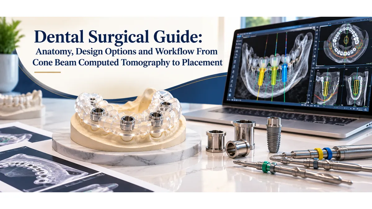
The surgical guide converts a digital implant plan into a physical tool the surgeon holds during drilling. It directs the handpiece at the exact angulation, depth, and position the software specified, and without it the precision built into the planning workflow has no way to reach the patient. Understanding what a dental implant surgical guide is made of, how support type affects accuracy, and how the full workflow moves from scan data to guide delivery helps clinicians make better case-planning decisions and communicate more clearly with their fabrication lab.
This guide covers the anatomy of a dental surgical guide from the body structure to the metal sleeves, the three primary support types and how to choose between them, open versus closed guide architecture, sleeve and drill protocol matching, and the complete workflow from cone beam computed tomography scan to chairside use.
The Anatomy of a Dental Surgical Guide
The Guide Body and Support Surface
Every dental surgical guide consists of two functional zones. The support surface is the portion of the guide that contacts the patient, whether that is the occlusal and interproximal surfaces of teeth, the contour of the soft tissue ridge, or the surface of exposed alveolar bone. This surface is derived directly from the patient scan data and must match the anatomy precisely for the guide to seat in its intended position.
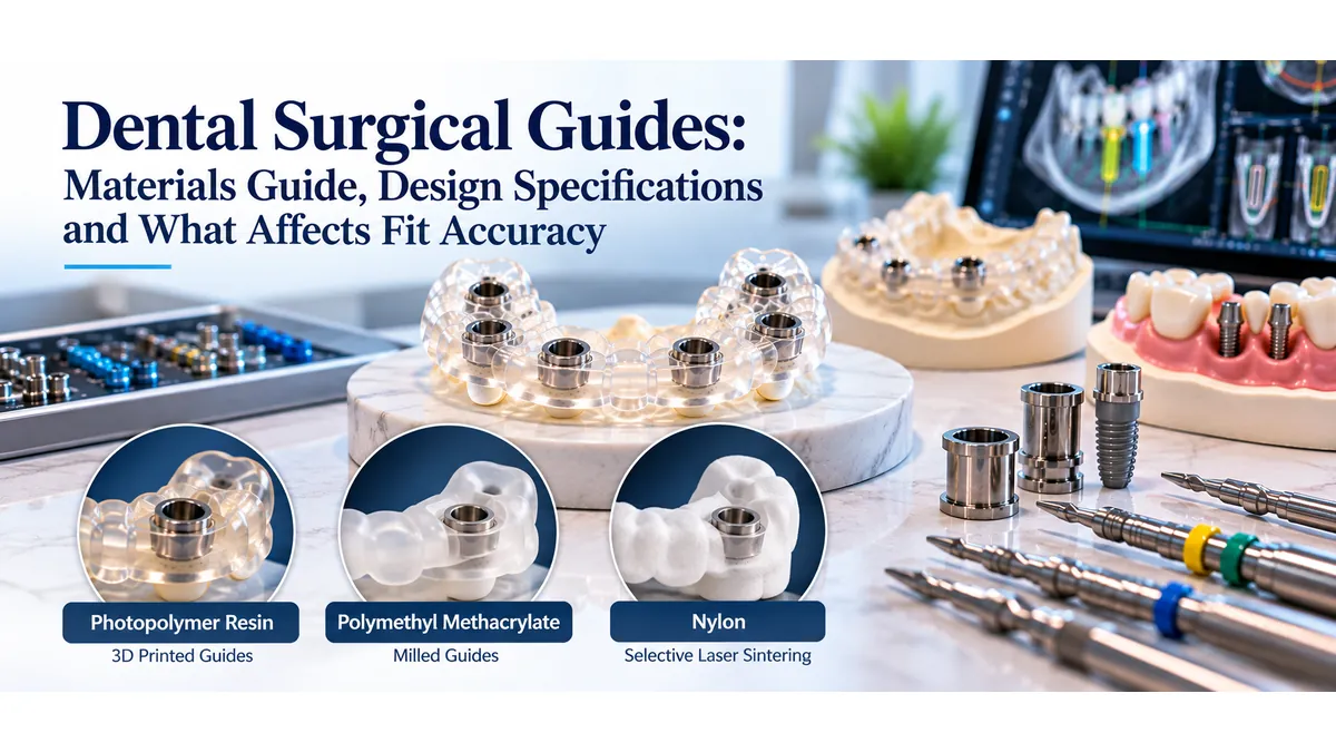
The guide body is the structural shell that connects the support surface to the sleeve housings. In most contemporary guides, the body is fabricated from biocompatible photopolymer resin using three-dimensional printing. Resin selection matters: the material must be certified for intraoral use, resistant to the surgical irrigation fluids used during drilling, and strong enough to resist deformation under the lateral forces of the drill. Reputable surgical guide design services specify resin grade in their fabrication protocols.
Guide Tubes and Metal Sleeves
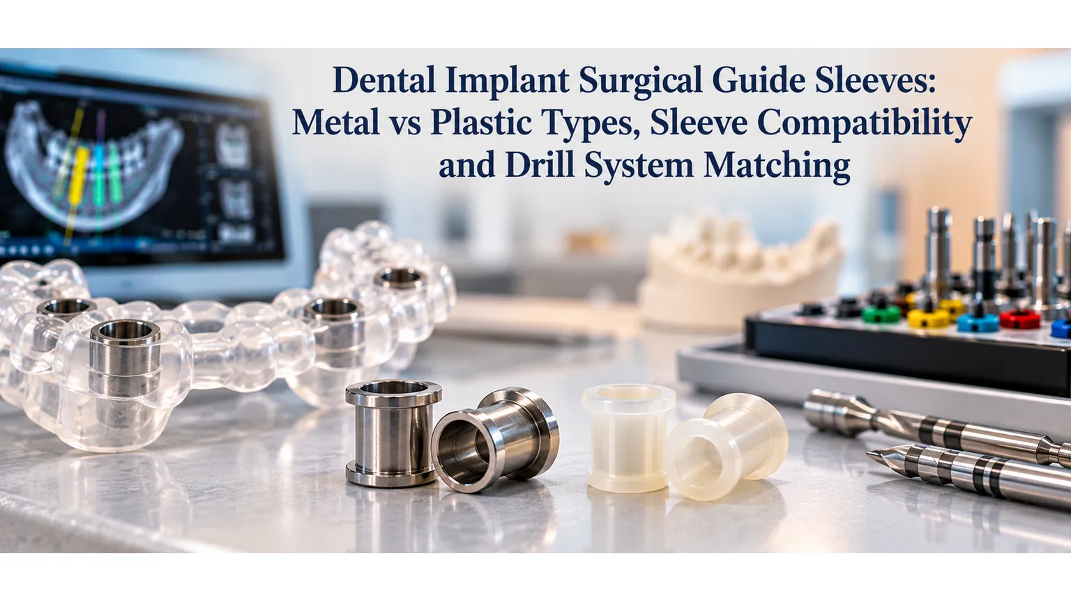
Metal sleeves are the precision components inserted into the guide body at each planned implant position. They are machined from stainless steel or titanium to tight dimensional tolerances, because the inner diameter of the sleeve is what physically constrains the drill. A sleeve with the correct inner diameter centers the drill at the virtual implant axis and prevents lateral movement during osteotomy preparation.
The sleeve is pressed or bonded into a printed housing in the guide body. The housing must be thick enough around the sleeve to prevent fracture during drilling. A housing that is too thin, or positioned too close to the edge of the guide, is a fabrication flaw that may not be visible on inspection but will cause guide failure under surgical load.
Fixation and Stability Features
Many guide designs incorporate anchor pin holes, which allow the surgeon to place small fixation pins through the guide and into the bone or into existing tooth structure to stabilize the guide during drilling. These are especially important in mucosa-supported and bone-supported guides, where the guide does not seat on rigid tooth surfaces. Without fixation, a guide that shifts even slightly between implant positions compromises the accuracy of each placement.
Tissue relief channels are recesses cut into the support surface to prevent the guide from rocking over soft tissue prominences. A guide that rocks does not seat accurately, and any measurement taken with an unseated guide is invalid. Verifying tissue relief adequacy is part of the design review step at a dedicated implant surgical guide lab.
The Three Support Types: Choosing the Right Foundation
Tooth-Supported Guides
Tooth-supported guides are the most accurate of the three primary categories. The guide seats on the occlusal and interproximal surfaces of the patient's remaining teeth, which provide a rigid, dimensionally stable reference. Because teeth do not compress under load and their surfaces can be captured in high resolution with an intraoral scanner, the guide-to-anatomy fit is predictable and verifiable before surgery begins.
This design is appropriate for partially edentulous patients with sufficient teeth adjacent to or surrounding the implant site. The bordering teeth must be in good condition: mobile, heavily restored, or freshly extracted teeth introduce variability in the seating reference. A minimum of two stable teeth on each side of the surgical site is the general guideline for reliable tooth support.
Mucosa-Supported Guides
Mucosa-supported guides seat on the soft tissue surface of an edentulous arch. Because soft tissue compresses, deforms with pressure, and varies in thickness across different areas of the arch, this support type introduces more inherent variability than tooth support. Accuracy depends on the quality of the intraoral scan capturing the tissue surface, the precision of the radiographic guide used during the cone beam computed tomography scan, and the patient's ability to maintain a consistent tissue position between scanning and surgery.
Anchor pin fixation is almost always required with mucosa-supported guides. Without it, soft tissue compression during drilling shifts the guide off its scan-derived position, and the shift is not predictable in direction or magnitude. Mucosa-supported designs are most common for full-arch cases where no teeth remain and bone-supported access requires a more extensive surgical approach.
Bone-Supported Guides
Bone-supported guides bypass the soft tissue entirely and seat directly on the surface of the alveolar bone after flap elevation. This provides a rigid seating reference that is unaffected by tissue compression, and it allows the surgeon to verify complete seating visually by inspecting the bone-guide interface.
The trade-off is surgical exposure. Bone-supported cases require a full mucoperiosteal flap, which increases tissue trauma, extends healing time, and is not suitable for flapless protocols. These guides are most appropriate for fully edentulous cases where bone anatomy is irregular, where tissue support would be unreliable, or where a hybrid tooth-and-bone design is required for a complex mixed dentition case.
Hybrid Designs
Some cases call for a guide that uses both tooth support and bone support in the same arch, typically when the available dentition does not provide sufficient bilateral stability. Hybrid designs require careful attention to the merge between the two seating surfaces, and they are more technically demanding to design and verify than single-support-type guides. Discussing the case anatomy with the fabrication lab before finalizing the support type prevents mismatched designs.
Open vs Closed Guide Architecture
Open-Frame Design
An open-frame or skeletonized guide removes material from the body wherever it is not structurally necessary, leaving windows over the occlusal surfaces and labial or buccal aspects of the guide. This architecture allows direct visual access to the surgical site during drilling, better irrigation flow to cool the drill, and easier access for the handpiece in cases with limited interocclusal space.
Open-frame guides are the dominant design in contemporary implant surgery. The reduction in material also reduces the weight and bulk of the guide, which contributes to patient comfort and easier seating verification. The structural frames connecting the sleeve housings to the support surface must maintain adequate wall thickness despite the material removal, which is a design parameter the fabrication software calculates automatically based on the specified material properties.
Closed-Top Design
Closed-top guides cover the occlusal surface fully, which increases overall stiffness and can provide additional stability in designs that span a long edentulous span. The closed top also protects the seating surface from contamination during the surgical procedure. However, closed designs limit direct visibility to the implant site and restrict irrigation access, which can increase heat generation at the drill tip.
Closed-top designs are less common in fully digitally fabricated guides but may appear in older systems or in cases where the bridge span between implant sites creates a structural concern that the open-frame geometry cannot address. Most current planning software defaults to open-frame unless specified otherwise.
Sleeve Systems and Drill Protocol Matching
Metal Sleeve Inner Diameter Specifications
The inner diameter of the sleeve is the most critical dimensional specification in dental surgical guide fabrication. Each implant manufacturer publishes a drill protocol that specifies the exact inner diameter required for each drill in the sequence. If the sleeve inner diameter is even 0.1 millimeters too large, the drill can deflect laterally inside the sleeve, shifting the osteotomy axis relative to the planned position. If the diameter is too small, the drill binds or cannot be inserted.
Sleeves are manufactured in a range of standard inner diameters corresponding to the drill protocols of major implant systems. A fabrication lab working with a verified sleeve inventory matched to specific implant brands can confirm diameter compatibility before printing. A lab that fabricates guides without explicit sleeve protocol verification is a risk for the clinician.
Sleeve Height and Tissue Offset
Sleeve height determines the distance from the bottom of the sleeve to the crest of bone or tissue at the implant site. This offset must account for the thickness of soft tissue the drill passes through before reaching bone in a flapless case, or the distance from the sleeve to the bone crest in a flapped case. Incorrect offset values produce a drill depth that does not correspond to the planned implant position.
Most planning software calculates sleeve height automatically based on the tissue thickness measured in the merged scan. The clinician reviews and confirms this value before exporting the guide design. Any discrepancy between the scanned tissue thickness and the actual tissue thickness at the time of surgery, for example due to swelling or a change in the patient's tissue height since scanning, introduces error in the final implant depth.
Stackable Sleeve Systems
Some implant systems use stackable sleeves, where a primary sleeve seats in the guide body and one or more secondary sleeves stack on top to guide progressively larger drills. Each stacked sleeve has its own inner diameter matched to a specific drill in the sequence. Stackable systems allow a single guide to direct the full drill sequence without removing and reinserting the guide between steps, which reduces the chance of guide displacement between drills.
Full Workflow From Cone Beam Computed Tomography to Guided Placement
Step 1: Cone Beam Computed Tomography Scan and Radiographic Guide
The workflow begins with a cone beam computed tomography scan taken while the patient wears a radiographic guide. The radiographic guide is a clear acrylic duplicate of the planned prosthetic tooth position, loaded with radiopaque markers. Its tooth positions appear in the three-dimensional scan data alongside the bone, giving the planning software both the bone anatomy and the prosthetic target in one dataset.
Scan field of view is selected based on case scope: a single-implant case uses a limited field for higher resolution, while a full-arch case uses a larger field. Scan parameters are set to minimize artifact around existing metal restorations without sacrificing spatial resolution at the implant sites.
Step 2: Intraoral Scan and Data Merge
An intraoral scan captures the surface geometry of the patient's teeth and soft tissue in STL format. This file is then merged with the cone beam computed tomography DICOM data in the planning software, aligning the two datasets at common tooth surface reference points. The merged dataset gives the planning software a complete view: bone anatomy in three dimensions, tissue surface contours, and prosthetic targets from the radiographic guide.
Merge accuracy is verified by reviewing the alignment at multiple cross-sections. Visible misalignment at any viewing angle requires a re-merge before planning proceeds. An inaccurate merge produces a guide whose support surface does not match the patient's actual anatomy, and that guide will not seat correctly at surgery.
Step 3: Virtual Implant Planning and Guide Design Export
With merged data confirmed, the clinician places virtual implant replicas at the planned positions, verifies bone margins, prosthetic space, and adjacent anatomy, and finalizes the plan. The planning software then generates the guide design: sleeve positions, support surface geometry, anchor pin locations, and body architecture. The completed design is exported as an STL file and submitted through the surgical guide submission process with the implant manufacturer's drill protocol and the merged scan file for lab review.
Step 4: Lab Review, Fabrication, and Sleeve Fitting
At the fabrication lab, the design file undergoes a technical review before printing. The review confirms sleeve placement, inner diameter matches the submitted drill protocol, wall thickness is sufficient at all points, and the support surface geometry matches the patient scan. A custom implant surgical guide lab contacts the clinician before fabricating if any design parameter falls outside specification.
After approval, the guide is printed, post-processed, and fitted with metal sleeves. Post-processing includes resin cleaning, post-curing to full material hardness, and inspection of the seating surface. Sleeves are pressed into their housings and verified for rotational stability.
Step 5: Chairside Verification and Surgical Use
On the day of surgery, the guide is seated on the patient and verified before drilling begins. For tooth-supported guides, full seating is confirmed visually and with gentle finger pressure at each support tooth. For mucosa-supported guides, anchor pins are placed through the guide before drilling to lock it in position. For bone-supported guides, seating is verified after flap elevation by inspecting the bone-guide interface around the full support surface perimeter.
Drilling proceeds through the sleeve sequence specified in the drill protocol. The handpiece shank seats in the sleeve at each drill diameter, and depth is controlled either by the sleeve height offset or by a depth stop on the handpiece attachment. Irrigation flows through the open guide windows. The implant is placed at the depth and angulation the plan specified, and the guide is removed.
Common Guide Design Errors and How to Avoid Them
Most guide failures trace back to four design errors, all of which are preventable with thorough review before fabrication. The first is inadequate tissue relief, where the support surface contacts a tissue prominence and causes the guide to rock rather than seat flush. The second is a sleeve inner diameter that does not match the submitted drill protocol, which causes binding or lateral deflection at the drill tip. The third is insufficient wall thickness around a sleeve housing, which leads to housing fracture under surgical load. The fourth is a scan-to-guide discrepancy caused by a poorly merged cone beam computed tomography and intraoral scan dataset. Understanding the surgical guide fabrication workflow and what the lab checks before printing helps clinicians know which errors have already been caught and which require chairside verification.
Clinicians can reduce error risk on their end by submitting complete case files (design STL, planning file, drill protocol, and intraoral scan), specifying the implant system and fixture diameter explicitly, and confirming tissue thickness measurements in the planning software before export. A thorough submission prevents the back-and-forth that delays fabrication and increases the chance of a miscommunication working its way into the finished guide.
Why Guide Design Quality Determines Surgical Outcome
The surgical guide is the only physical object in the guided surgery workflow. Every other element, the cone beam computed tomography scan, the intraoral scan, the virtual plan, the planning software report, exists as data. The guide is what the surgeon uses in the operatory, and its accuracy determines whether the implant goes where the plan said it should. Working with dental implant guide design specialists who verify each design parameter before fabricating ensures that the precision of the digital plan is preserved through to the finished guide.
A well-fabricated guide from a verified design places the implant at the planned position within the system's stated accuracy range, typically within 1 millimeter at the platform and 2 degrees of angulation. A guide fabricated from an unverified design or by a lab without surgical guide specialization can produce errors that exceed those tolerances, putting the implant outside the prosthetic envelope and creating restorative complications that the digital plan was specifically built to avoid.
Conclusion
A dental surgical guide is a precision instrument, and every component from the support surface to the sleeve inner diameter contributes to its accuracy. The support type determines the seating reference, the guide architecture determines visibility and irrigation access, the sleeve system determines drill control, and the fabrication quality determines whether the design tolerances are actually met in the physical object. Understanding how these elements work together helps clinicians choose the right design for each case and evaluate whether a guide was built to specification before it reaches the operatory.
The workflow from cone beam computed tomography scan to placed implant is only as accurate as the weakest link in the chain. A thorough design review at the lab stage, matched drill protocols, and verified sleeve specifications are what close the gap between planned and actual implant position.
To see how Guided Excellence handles design review and fabrication, review the guided surgery workflow and fabrication process before submitting your next case. When you are ready to begin, submit your surgical guide case files through the case portal, or contact the Guided Excellence team to discuss case-specific design questions. For a full overview of available guided surgery options, visit the implant surgical guide services page.