
A surgical guide appears to be a simple device, a custom-shaped resin template with metal tubes that direct a drill. In reality, it is a precision instrument with multiple interdependent design parameters, each of which contributes to or detracts from the accuracy it delivers in surgery.
Understanding these parameters matters for two reasons. First, it helps you communicate specific requirements to your guide laboratory. Second, it helps you recognize when a guide's design may be contributing to accuracy problems, rather than attributing all variability to surgical technique.
Parameter 1: Drill Sleeve Inner Diameter
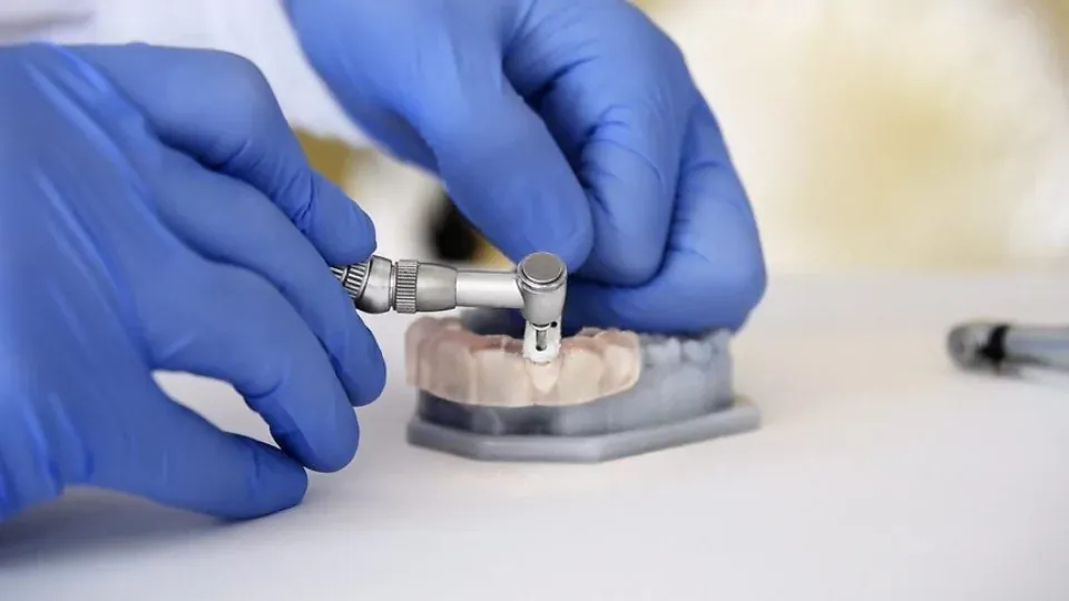
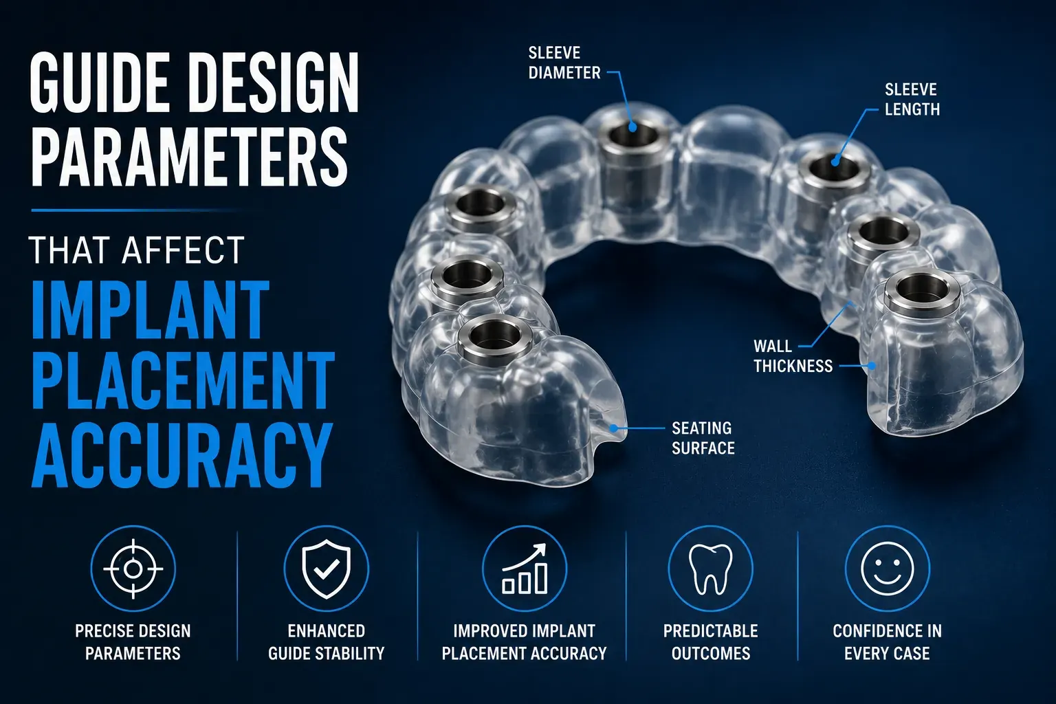
The drill sleeve inner diameter is the most mechanically consequential parameter in the entire guide. It must match the drill diameter for your specific implant system to a tolerance of plus or minus 0.05 to 0.1mm. The physics explain why this precision matters so much.
When a drill is inserted into a sleeve with 0.2mm excess diameter on each side (a total of 0.4mm diameter excess), the drill can pivot within the sleeve. A 0.4mm pivot allowed at the sleeve level translates to approximately 0.8 to 1.5mm positional error at the implant apex for a standard 10mm osteotomy depth. That single parameter deviation can eliminate half or more of the accuracy advantage that guided surgery is supposed to provide.
At Guided Excellence, every sleeve inner diameter is measured with precision bore gauges before insertion, not assumed from supplier documentation. This is standard practice in our implant surgical guide lab, not an optional QC step.
Parameter 2: Sleeve Length
The sleeve must be long enough to guide the drill along a meaningful portion of its path, not just at the entry point. A sleeve that is too short provides directional control only at the surface of the guide, allowing angular deviation to develop freely below the sleeve.
Standard sleeve length for surgical guides is 6 to 10mm. Longer sleeves provide more angular constraint but require more vertical space, which can be problematic when interocclusal space is limited. The design must balance adequate sleeve length against the anatomical constraints of each specific case.
Parameter 3: Guide Body Wall Thickness
The guide body must be rigid enough to maintain sleeve positions accurately under the drilling forces of surgery. If the guide body flexes or deforms during drilling, the sleeves shift from their designed positions and accuracy is lost.
Minimum wall thickness guidelines:
- Seating surface areas: 4 to 6mm for structural integrity under occlusal and drilling forces
- Guide body walls: 2 to 4mm as a balance between rigidity and bulk
- Areas around sleeves: minimum 1.5mm of material surrounding each sleeve for structural support
- Full arch guides: thicker construction throughout due to larger forces and longer lever arms
Guides with inadequate wall thickness may appear structurally sound during casual inspection but flex dynamically under drilling. This dynamic flexing is invisible to the surgeon but creates cumulative positional error across a full drilling sequence.
Parameter 4: Seating Surface Design and Contact Area
The seating surface is the part of the guide that contacts the patient's anatomy. Its design determines whether the guide seats passively and stably, or whether it rocks, shifts, or requires force to position.
For tooth-supported guides, the seating surface must conform precisely to the occlusal and buccal contours of adjacent teeth. The contact area should be maximized to distribute seating stability over as broad a base as possible. Guides that contact only one or two tooth surfaces are inherently less stable than guides that contact multiple teeth.
For mucosa-supported guides (edentulous cases), the seating surface must conform to the ridge anatomy with broad contact and must account for tissue compressibility, soft tissue compresses under drilling forces, which can shift the guide position if retention is inadequate.
Every seating surface designed by Guided Excellence is verified against the patient's three-dimensional model before fabrication. The custom surgical guide design process includes a model fit test on every finished guide before shipment.
Parameter 5: Implant Angulation in the Guide
The angulation of each drill sleeve defines the angulation of the implant. Sleeve angulation is determined during virtual planning to achieve the prosthetically optimal implant axis while remaining within the available bone envelope.
Angulation accuracy requirements:
- Straight implants: sleeve axis must match planned implant axis within 1 to 2 degrees
- Angled implants (All-on-4 posterior): sleeve axis must match planned angulation within 2 to 3 degrees
- Angular deviation compounds with depth: 3 degrees of sleeve tilt at a guide surface 3mm above bone creates approximately 0.5mm positional deviation at 10mm implant depth
Angular parameters interact with sleeve length. A longer sleeve that is slightly off-angle creates more apex deviation than a shorter sleeve at the same angle. This is why both sleeve length and sleeve angulation must be precisely controlled simultaneously.
Parameter 6: Depth Stop Position
The depth stop is the mechanical feature within the sleeve that halts the drill at the planned implant depth. Its position is calculated from the planned implant depth, adjusted for the offset between the guide surface and the bone entry point, and further adjusted for the implant tip geometry of the specific system being used.
Depth stop accuracy is particularly critical in mandibular posterior cases where the inferior alveolar nerve must be avoided, and in maxillary posterior cases where the sinus floor clearance must be maintained. An incorrectly positioned depth stop can expose the patient to exactly the anatomical risks that guided surgery is designed to prevent.
Parameter 7: Sleeve-to-Sleeve Distance in Multi-Implant Guides
When a guide contains two or more sleeves, the distance between sleeves affects both structural integrity and drilling ergonomics. Sleeves that are too close together weaken the guide body between them and can create structural failure under drilling forces.
Minimum sleeve separation is 1.5 to 2.0mm of material between sleeve walls. When case anatomy places planned implants closer than this minimum, guide design must compensate, typically through structural reinforcement around the closely-spaced sleeves.
Parameter 8: Retention Features
A guide that moves during surgery delivers inaccurate results regardless of how precisely it was designed. Retention features, the mechanisms that keep the guide in position under drilling forces, are a fundamental design parameter.
For tooth-supported guides, retention is provided by the conforming fit of the seating surface on tooth anatomy, optionally supplemented by retention pins that engage interproximal spaces or root surfaces. For mucosa and bone-supported guides, retention pins anchored in bone are typically required to prevent guide movement during surgery.
The adequacy of retention features is case-specific. Full arch cases, immediate extraction socket cases, and long multi-implant sequences all benefit from additional retention. When submitting cases to Guided Excellence, specify your surgical approach and any concerns about tissue resilience so our team can optimize retention design for your specific case. Submit your case here.
How Design Parameters Interact
These parameters do not operate independently, they interact. A guide with precise sleeve diameters but inadequate wall thickness will lose accuracy through body flex. A guide with excellent wall thickness but poor seating surface design will deliver inaccurate results because it seats inconsistently. A guide with perfect sleeve angulation but insufficient retention will shift under drilling forces.
This interdependency is why surgical guide design requires clinical expertise and systematic quality control, not just software automation. Software can optimize individual parameters; only clinical review and physical model testing can verify that all parameters interact correctly to produce a guide that performs as designed.
Dr. Baghoomian's personal review of complex cases at Guided Excellence exists precisely to apply this clinical judgment to designs before fabrication. Explore our complete guide design and manufacturing process to understand how every parameter is controlled.